

The following tutorial will guide you through the process of building your own data logger for reading temperature and humidity and storing it to the SD card at any given interval. We will use one of the most common Arduino boards for this project: the Arduino Uno. This tutorial is aimed for beginners who are new to the Arduino platform.
Note: If you’re not familiar with how a breadboard works, check out a simple tutorial by SparkFun.
Difficulty Level: Beginner
STEP #1: What you’ll need:
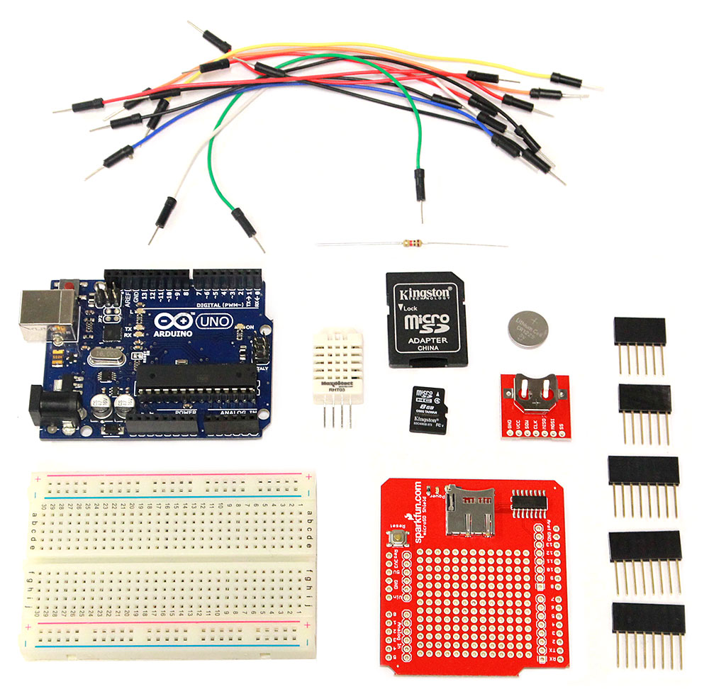
Hardware requirements:
Arduino Uno Starter Kit (includes Arduino Uno, breadboard, jumper wires and USB cable A to B)
DeadOn RTC DS3234 Breakout from Sparkfun
CR1225 coin cell battery for the RTC
RHT03/DHT-22 Humidity and Temperature sensor
Sparkfun microSD Shield Retail (includes headers)
1 kΩ resistor
microSD card (any capacity)
Soldering iron
Software requirements:
Arduino IDE 1.0.5 or higher (for Windows or Mac OS X or Linux)
Adafruit DHT sensor library
DS3234 RTC library
STEP #2: Hardware Setup
1. Our first step in setting up the hardware will tackle the data storage problem of existing dataloggers. We will store our data in a microSD card of any capacity. For this, we will use a microSD shield for the Arduino Uno. The SD card shield saves data files in .csv format and the data is in plain text. Due to this, the file size is extremely small, and using a microSD card even as small as 1 GB should be sufficient to store many years worth of data.
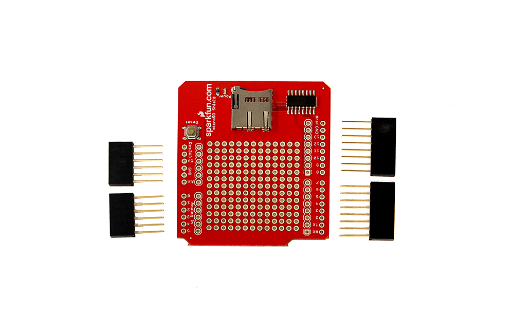
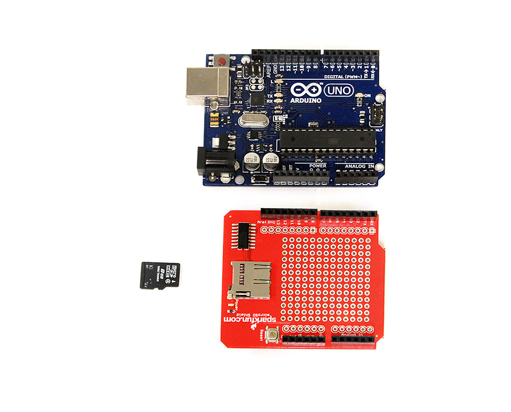
The microSD card shield from SparkFun comes with 4 headers (two 6 pin and two 8 pin headers). These must be soldered to the shield before it can be used. After soldering the headers, we can just mount the shield on top of the Arduino Uno. It is interesting to note that the pins on the SD card shield are the same pins on the Arduino Uno. The only pin that the shield actually uses is the digital pin 8. If you’re using the microSD card shield and the SD card library, Do not use this pin for anything else.
2. The DeadOn RTC DS3234 Breakout is an extremely accurate Real-Time Clock which helps us to keep track of time while recording data. It has a slot for a 12mm coin cell battery, which can provide power to the clock in the absence of external power. This RTC comes with its own library which needs to be installed in your computer (explained in Step 3). The date and time have to be initialized once using a very small block of code, which will be explained in Step 4 of this tutorial. Alternatively, you can also use the slightly less accurate, but cheaper DS1307 RTC.
Setting up the RTC consists of two simple steps:
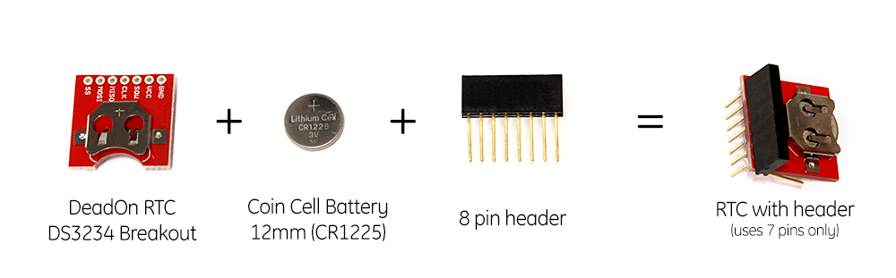
i) Solder the 8-pin header to the RTC.
(Note that the RTC has 7 holes only. Since female headers are available in 6 pins, 8 pins and 10 pins only, we can take an 8-pin header and bend the last pin so it fits the RTC. Alternatively, we can even use male headers.)
ii) Insert the 12mm coin cell battery into the RTC.
Now let’s take a closer look at the RTC:
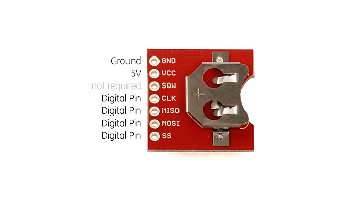
There are seven pins in total on this RTC. Each pin has a unique label right next to it. These will help us when we connect the RTC in the circuit. The pins marked SS, MOSI, MISO and CLK can be connected to any of the digital pins on the Arduino. Take note of the actual pin number on the arduino, as we will be using them in our code to set up the RTC. The pin marked SQW can either be connected to ground or can be ignored. (Note that connecting the ground and power pins incorrectly may reset the time on the RTC and you may need to set it up again.)
3. For measuring the temperature and relative humidity, we will use the DHT-22 (also called RHT03) sensor. This is a digital sensor that has great value for money. It is pre-calibrated, so the readings from the sensor are pretty accurate. In order to make the readings even more precise, we will calibrate the sensor further to an Onset HOBO U12.
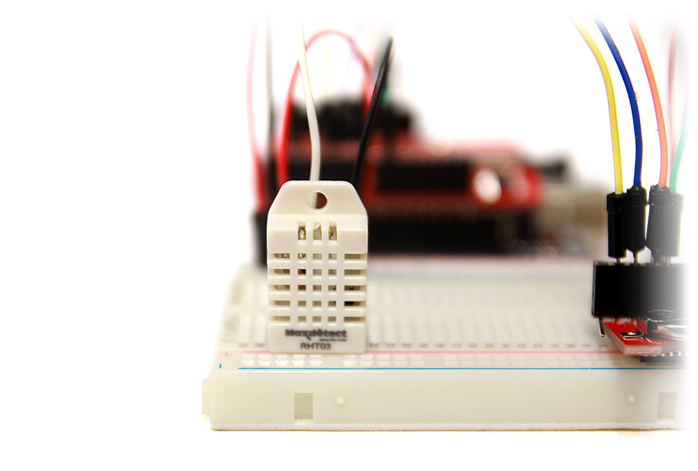
Although this sensor has four pins in total, only three pins are actually used. Two pins serve as power and ground, while a third is connected to a digital pin on the arduino for acquiring data. Since this is a digital sensor, it also requires an arduino library (explained in Step 3). A 1,000 ohm (or 1 kΩ) resistor must be connected between the digital pin and the power pin. (Note that the DHT-22 sensor has extremely sensitive pins. Even slight damage to the pins may yield incorrect results)
The circuit for setting up the DS3234 RTC and DHT-22 sensor is shown below:
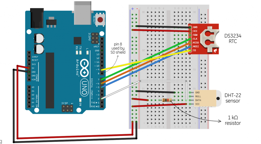
(Image was created using Fritzing and modified in Adobe Photoshop. Click the image for a larger view.)
Note that the circuit shown above will be assembled in the same way, except our Arduino will now have a microSD card shield mounted on top on which the wires are actually connected.
A few other things to note here:
* In the circuit above, ground (-) is shown as the black wire and power (+) is shown as the red wire.
* The digital pins used in our circuit are marked as follows:
Temp/Rh sensor – 2
SS – 5
MOSI – 6
MISO – 7
CLK – 9
STEP #3: Installing Arduino IDE and libraries
For this project, we will need to download and install the Arduino IDE. This is the Arduino environment on which you can write code and upload it to your Arduino board. The latest version at the time of writing this tutorial was 1.0.5. The Arduino IDE works on Windows, Mac OS and Linux. After the installation of the Arduino IDE, we will download specific libraries for the RTC and the DHT-22 sensor. Installation of these libraries is as simple as extracting all files from the zip file into the “libraries” folder located inside your Arduino IDE installation directory. For example, in Windows, this may be located in C:\Program Files\Arduino 1.0.5\libraries\.
STEP #4: Initializing date and time in the RTC
Now that we have our Arduino IDE and the libraries installed, we will need to set the current date and time in the RTC. Let’s open up the Arduino IDE and create a new project.
First, we define the library we want to use:
#include<DS3234.h>
Now we go into our setup() function. We will configure the digital pins our RTC is connected to. This is done as follows:
RTC.configure(6,7,9,5);
The order of pins defined in this function goes as follows: MOSI, MISO, CLK, SS. In our example, we connected MOSI to pin 6, MISO to pin 7, CLK to pin 9 and SS to pin 5. Depending on which pin you connected each to, you’ll need to define it in the code respectively.
Next, we will configure the date and time of the RTC:
RTC.setDateTime(21,2,14,18,30,0);
The order of defining is as follows: Day, Month, Year, Hour, Minute, Second. Note that the time in this RTC is always expressed in 24-hour clock. The above example code will define the date as 21st February, 2014 and the time as 6:30:00 PM. Now we will upload this code to the Arduino. Connect the Arduino to the computer via USB. In the Arduino IDE, go to Tools>Serial Port from the menu and make sure you select the proper COM port which your Arduino Uno is connected to. Click on the Upload button (or go to File>Upload) and wait for the code to compile, verify and upload. Usually this takes a few seconds. If the code is set up properly, it will display “Done Uploading” at the bottom. And that’s it, your RTC is now setup and the clock starts working.
Here’s the complete sketch for setting date and time in the RTC:
#include <DS3234.h>

void setup()
{
  Serial.begin(9600);
  RTC.configure(5,6,7,9);
  RTC.setDateTime (11,3,14,13,39,0);
}

void loop()
{
  Serial.println(RTC.readDateTime());
  delay(1000);
}
Note that the setup() and loop() function are a necessary part of any Arduino code even if they don’t contain anything. This only has to be done once if you’re using the RTC with the coin cell battery. Once set, it will work as a proper clock, with an accuracy of around a couple of seconds every year.
STEP #5: Programming the datalogger
Now that we have our RTC running, we’ll create the main program logic for reading temperature and humidity data at regular intervals and storing it to the SD card.
Let’s create a new project file. First, we’ll add all the header files and libraries required:
#include "DHT.h"
#include <SD.h>
#include <Wire.h>
#include <Time.h>
#include <DS3234.h>
Next, we make an instance of our sensor from the DHT library.
DHT sensor;
The instance name “sensor” can be replaced with any word.
Now, we’ll initialize our variables that we use in our program. We do this before everything to ensure we can use them anywhere in the code (i.e., global variable).
int ID = 1;
int h = 16, m = 46, s = 0; // set the logger's launch time in 24-hr clock
float temp, rh;
Here, the ID is an integer variable that just stores the ID number of the data point. The variables “h”, “m” and “s” relate to hour, minute and second respectively. This is a user-defined start time of our sensor. In our example code above, the sensor is set to start at 7:00:00 PM. This can be changed accordingly. The variables “temp” and “Rh” store the actual temperature and humidity values recorded from the sensor. These are initialized as “float”, as they have decimal point accuracy.
Now that our variables and headers are initialized, let’s create the setup() function.
void setup()
{
  delay(500);
  RTC.configure(5,6,7,9);
  sensor.setup(2);
  pinMode(10, OUTPUT);
  SD.begin(8);
  Serial.begin(9600);
  Serial.println("Ready");
  PrintHeader();
  CheckTime();
}
Arduino is based on procedural-oriented programming by default, which means it executes code line-by-line. In order to avoid any error while executing the code, we add a small delay (500 ms in our case) in the very beginning. As you get more familiar with the Arduino platform, you’ll learn to control and use delays efficiently.
We configure our RTC pins again in the code. We also initialize our sensor pin (pin #2 in this case). The SD card shield from SparkFun has the CS pin defined on pin #8. However, most SD card libraries assume the CS pin to be defined on pin# 10. Due to this, we set pin #10 as output. We also have two custom functions called PrintHeader() and CheckTime(), which are explained below.
The PrintHeader() function will print a header in the file saved on the SD card.
void PrintHeader() // this function prints header to SD card
{
   File datafile = SD.open("Alpha.csv", FILE_WRITE);
   if (datafile)
   {
      String header = "ID, Date, Time, Temperature (C), Humidity (%)";
      datafile.println(header);
      datafile.close();
      Serial.println("Header Printed");
   }
   else
   {
     Serial.println("ERROR: Datafile or SD card unavailable");
   }
}
Here, a file name “Alpha” is created (the name can be replaced with anything). The file extension used here is .csv. You can also create a .txt file if you wish. Note that running the code several times using the same file name will not replace the data contained within the file; it’ll append new data to it. This is how the SD library works by default.
The CheckTime() function is now defined:
void CheckTime() // this function checks if the specified start time has reached
{
   while(1)
   {
    RTC.readDateTime();
    if(RTC.time_h()==h && RTC.time_m()==m && RTC.time_s()==s)
    {
      Serial.println("Launch Time reached");
      break;
    }
   }
}
This function will continue looping until the RTC matches our set time. This will be our start time for recording data.
Let’s define the main loop() function. This function in Arduino will continue looping the block of code contained within it. This will help us to keep recording data without stopping.
void loop()
{
    RTC.readDateTime();

    if(s>=60)
    {
      s = s-60;  //reset s (seconds) to 0 after one minute or more has passed
      m++;  // add one minute after 60 seconds have passed
    }
    if(m>=60)
    {
      m = m-60;  //reset m (minutes) to 0 after one hour or more has passed
    }
    if(h>=24)
    {
      h = h-24;  //if time interval is greater than one hour
    }
    if(RTC.time_h()==h+1 || RTC.time_h()==0)
    {
      h = RTC.time_h();  //change value of h to actual hour after one hour or one day
    }

    if(RTC.time_h()==h && RTC.time_m()==m && RTC.time_s()==s)
    {
      Serial.print("Current Date & Time: ");
      Serial.println(RTC.readDateTime());
      GetData();
      CalibrateSensor(); // optional - not required
      ConvertToF(); // optional - not required
      PrintToSD();
      s = s + 10; // for 10 seconds intervals
      //m++; // for 1-min intervals
      //m = m+5; //for 5-min intervals
      //h++; // for 1-hour intervals
      ID++;
    }
}
The loop() function contains five if() statements. The first four if() statements are programmed to reset the custom integer values of “h”, “m” and “s” back to 0 or to to the proper interval defined. The last if() statement runs when the RTC time matches our interval time. The loop also calls three additional custom functions: GetData(), CalibrateSensor() and PrintToSD(). These functions are explained below. Note that using functions isn’t required; you can have your entire code in the loop function. Using functions helps in organizing your code better and debugging it easily if anything goes wrong.
In our loop() function, we set “m++” to define intervals of one minute. In this case, the function will save data and increment our “m” value, which corresponds to minutes, by 1. Then, it will continue to loop, until the RTC time matches our time, which is exactly after 1 minute. Once the time matches, it will record the data. The value is then incremented by 1 again and the function continues to loop accordingly. Note that “m++” is the same as “m = m + 1″.
We can specify any interval in place of this. For example, for 5-minute intervals, we can replace the “m++” line with:
m = m + 5;
Similarly, for 10-second intervals, we can write:
s = s + 10;
and for 1-hour intervals:
h = h + 1;
and so on. Now let’s define our custom functions, starting with GetData():
void GetData() // this function gets T/RH values from the sensor
{
  temp = sensor.getTemperature();
  rh = sensor.getHumidity();
}
The above function does exactly what it sounds like – it gets the data from the sensor.
void CalibrateSensor() // this function calibrates the sensor data with an Onset HOBO U12
{
  temp = 1.0107 * temp;
  rh = 0.8632 * rh;
  Serial.println("Sensor calibrated");
  Serial.print("Temperature: ");
  Serial.println(temp, 2);
  Serial.print("Humidity: ");
  Serial.println(rh, 1);
}
The above function will calibrate the data values with an Onset HOBO U12 in order to make them more accurate. This function is optional, as accuracy of each sensor may vary.
Finally, let’s define the function to save data to the SD card:
void PrintToSD()  // this function saves the data to the SD card
{
        File datafile = SD.open("Alpha.csv", FILE_WRITE);
        if(datafile)
        {
            datafile.print(ID);
            datafile.print(",");
            datafile.print(RTC.date_m());
            datafile.print("/");
            datafile.print(RTC.date_d());
            datafile.print("/");
            datafile.print(RTC.date_y());
            datafile.print(",");
            datafile.print(h);
            datafile.print(":");
            datafile.print(m);
            datafile.print(":");
            datafile.print(s);
            datafile.print(",");
            datafile.print(temp, 2); // printing temperature up to 2 decimal places
            datafile.print(",");
            datafile.print(rh, 1); // printing Rh up to 1 decimal place
            datafile.println();
            datafile.close();
            Serial.println("Data printed to SD card");
            Serial.println();
        }
        else
        {
            Serial.println("ERROR: Datafile or SD card unavailable");
            Serial.println();
        }
}
Here, we use the same file name we defined before.
If you want temperature values in Fahrenheit instead of Celsius, you can define a function that does that too:
void ConvertToF() // this function will convert temp values from degree Celsius to degree Fahrenheit
{
  float temp_f = (1.8 * temp) + 32;
  temp = temp_f;
}
Now we can upload the complete sketch into our Arduino. And that’s it, we’ve created a temperature and humidity datalogger! Pretty simple once you know how, right?
The complete sketch for programming the datalogger is available on GitHub.
STEP #6: Test Run
Now that we’ve created our own datalogger, we can leave it for a while and let it store some data. In order to read the data, it is as simple as putting the microSD card in an SD card adapter and plugging it in your computer. Microsoft Excel can read comma delimited .csv files and format the data in separate columns automatically.
Here are some data samples from our datalogger:
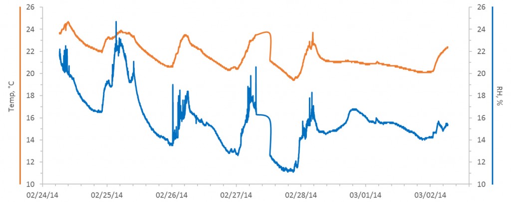
It is interesting to note how relative humidity has a dependence on temperature. With this datalogger, we are able to monitor long-term T/RH data in a room and explain all the paranormal phenomena going on.
We tested seven DHT22 sensors together, and it turns out that they aren’t very accurate. For normal applications, they work well, but if you’re looking to create your own T/RH datalogger for research purposes, we recommend checking our tutorial based on a more accurate sensor – the SHT15.